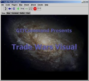
Trade Wars Visual

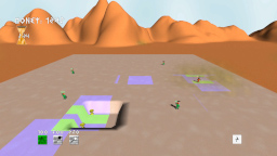
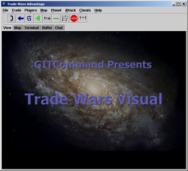
Trade Wars Visual is a Trade Wars helper that I wrote in Java around 2000.  It only supports web BBS connections, so it is not able to connect to dial-up BBSes.  The helper will track which sectors the player has visited, and it will create maps to illustrate the connecting sectors.  The intent was to create a fully visual Trade Wars experience.  The ability to navigate between sectors using mouse clicks is fully implemented, by selecting the sector previews at the top of the screen.  A text based terminal is also supplied to navigate menus not supported by the graphical interface.

A chat window is also provided, which simplifies sending messages to other players in the world or on your team.  It provides a complete chat log window, which is an improvement over standard VT100 terminals which cause chat messages to be lost with the game text.

Download Trade Wars Visual

This software is provided AS-IS with no warranty.

Source code not included.


New Attract Screens

I used Blender to render three models for the attract screens.  I decided to drop the first screen, so there are three total screens which display for 5 seconds each before the title screen is displayed.

I used my existing image of the B.A.N.G. logo as a guide to create the first model.  I rotated the camera slightly on the Z axis to give it more of a 3D appearance.  Then I rendered the image and exported it to a PNG file.  Eventually, I plan to use the actual model in the game.  I created a new background image in Gimp, using Script-Fu Lava as the background.  Using Colorize and Brightness-Contrast, I made the background image a light green color.  Then I pasted the rendered model image into a new layer, and entered the text on another layer.  Creating the raised text effect is sort of a pain.  First I entered the text in black.  Then I used the color chooser to select the text, and then I copy and paste the selection into a new layer.  With the new text still selected in the new layer, I fill the selection with the  light green color.  Finally, I slightly move the new text selection up and to the left 2 pixels.  I may end up rendering the text in real time using the ResistorKit drawRaisedString method, but it’s much easier to place the text in Gimp than placing it programmatically.


For the mass-to-binary converter screen, I just used a cylinder and extruded two wider cylinders on the top and bottom.  Also, I removed all the vertices in the inner cylinder to give it an open appearance.  I also placed a light green light source in the inner cylinder.


For the final digital world screen, I am just using a Blender ico-sphere with a texture mapped to it.  The texture is a bunch of 1’s and 0’s on a green background.  The wrapping didn’t turn out exactly right, so that’s something I will probably want to fix later.

Radiant Socket

http://www.youtube.com/watch?v=2qUl7osMM60

The Radiant socket allows the player to see more in a dark room.

Tonight, I started working on the first helmet socket, which is the Radiant socket.  This socket will allow the player to see in dark rooms.  In dark rooms with no sockets, the player will only be able to see their character.  With Radiant +1, the player can see enough to move around effectively, but it will still be difficult to see enemies.  Enemies can be seen from a distance with Radiant +2.  Almost all of the room can be seen with Radiant +3.

I found a good 2D Fog of War example, which helped me understand how to create the lighting effect.  First of all, I had to create a bitmap that represents the lit area.  This was created in Gimp by using the gradient tool with the radial shape option select.  Clicking on the gradient allowed me to select the color as FG to Transparent, with the FG set to pure white.  I loaded this gradient as a texture in the main class.  A new RenderTarget2D object also has to be created and initialized in the LoadContent method.


In order to draw the light gradient, I found that it is necessary to pass the RenderTarget2D and GraphicsDevice to the drawScreen method of the Screen.  Since ResistorKit doesn’t currently handle this, I just created a drawRadiant method in the GameScreen class.  I do a class comparison in the main draw method using the “is” operator to see if the current screen is GameScreen.  If the current Screen is a GameScreen, then it uses the drawRadiant method which takes the RenderTarget2D and GraphicsDevice as parameters, otherwise it uses the regular drawScreen method.  Ideally, I’ll go back and update ResistorKit to overload the drawScreen method to accept the additional parameters.

In the GameScreen class drawRadiant method, I first set the rendering target to the passed in RenderTarget2D.  Then I draw the light gradiant texture, with the BlendState.Additive option enabled.  I created a function in the Player class, which returns how big the radiant area should be, based on which Radiant socket is equipped.  Then it draws the gradient image based on the radiant size returned by the Player class.  I am also careful to draw the light gradient centered on the player based on their screen location.

Next, the render target gets set back to null, and the regular game world screen is drawn.  I extracted the status overlay into another draw method, which includes the health bar, debug information, and money display.  This is because I want those items to always be displayed regardless of radiant light size.

After drawing the game world screen, a BlendState object is created.  The two DestinationBlend properties are set to Blend.SourceColor, and the two SourceBlend properties are set to Blend.Zero.  I don’t fully understand this, but that’s how it is set up in the example and it works.  Now the lighting effect is drawn using another call to SpriteBatch.begin, but this time the BlendState object is passed as a parameter, and the RenderTarget2D object is passed as a parameter to the Draw method.

Finally, I call the SpriteBatch.Begin method again with no parameters and call the Status Overlay drawing method that I created to draw the health bar and debug information.

I also did a little more work on modeling in Blender, by starting on a new player model.  I’m hoping that this one will end up looking a little more realistic.