Multiple Wire Problem
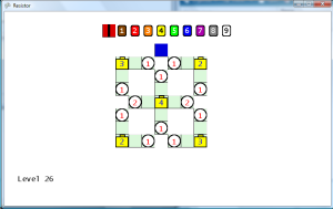
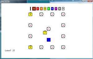
Noticed a problem that doesn’t happen too often, but when it does it is really annoying. This is when you place a wire (or resistor) next to two filled wires with different flow values. For instance, if I place a wire where the blue square is in the first image below, then what flow value should the new wire get? Should it be a 3 from the left wire or a 5 from the right wire? Remember, this is my puzzle/arcadey game rules, and not a real simulation so I get to make up the rules. Currently, it just uses the value of the first check in the if/elseif/else block. However, this is ambiguous to the player, because the player can’t determine what the value of the wire placed will be. That’s unless they’re clever enough to figure out that the cells are evaluated in a clockwise manner starting at the top. So currently the new wire would get a value of 5 from the right wire. However, if the wire were placed in the blue square in the second image, then the new wire would get a value of 3. This was confusing me as I play tested the game, so I’m sure it would also confuse other players as well.
Therefore, in the checkStartFilling method in the GameLevelScreen class, I added a loop that calculates the highest value of all the adjacent cells, and uses that highest value for the new wire. In the two images below, now placing a wire in the blue square will set the new wire’s value to 5 in both cases, since 5 is greater than 1. It’s not realistic, but a least the player can clearly anticipate what the value will be now.
Connection Problem
This logically fixed the problem, but the display was still misleading, because it would make a complete loop with two different flow values in the loop.
To fix this problem, I updated the draw method in the GamePiece class to only make connections to wires with the same flow value. The resistor wires are a little tricky, because it’s difficult to determine which wires carried the flow in and which ones carried the flow out. Another visual distortion happened when two wires with different values were placed next to each other that only had one joining wire each. Those appeared to connect since the default image for a wire with only one connection spanned all the way across the cell horizontally. Therefore, I made wire images specifically for only one connection (N, E, S, W) on each side and an image for a no connection wire ( O ) to resolve this issue. These new images provide a few pixels for a break padding, so that those wires don’t appear to be connected to pieces that they are not connected. Now as shown the in the screen shot below, with the updated code and images the user can clearly see the flow through each of the wires, and there is no doubt that the value of the wire in the blue square is now 5.
Game Win Screen Updated
Moved the game win display code to the game win screen, to make it consistent with the other screens. To to this, I had to pass the piece count, luminosity, and time values to the Game Win screen. Additionally, I had to pass a reference to the level definition object, so that the rank values can be calculated. I also added a win delay on the Game Level screen, so that there is a one second pause between the time when the last LED is activated and when the Game Win screen is displayed.
More Level Design
Created twenty new levels (21 to 40). I purposely designed some of the levels to force the player to use the higher level resistors (2, 3, and 4). I increase the highest level battery used by one for each ten levels. One flaw that I’m making in level design is making it so that every tile must have a piece to clear the stage. Technically, this is fine but the user will always get an S rank in pieces used. Therefore, I should always include a few tiles that don’t have to be used, so that there is a chance for lower piece ranks.
During play testing, I noticed that one level didn’t have any tiles and only objects. This was due to me exporting the wrong layer as the tile layer. Going back and exporting the correct layer resolved this problem.
High Level Resistors
The player now starts out with only one selectable resistor (value 1). Every 10 levels, the maximum selectable resistor increases by one. This prevents the player from using a high level resistor to lower the initial wire to zero, which would allow the player to quickly complete the level.
(Gray video distortion fixed. Thanks to tip from SHADEE.)


